
How to Choose the Right Spindle Motor Shaft?
Choosing the right Spindle Motor Shaft is a precision decision, not a simple purchasing task. The shaft transfers torque, supports the tool holder, and influences runout, vibration, heat, and surface finish. A small mismatch can appear as chatter, tool marks, or premature bearing wear.
Dr. Tony Schmitz, a respected machining dynamics researcher, describes the spindle as “the heart of the machine tool.” That view is practical. The shaft must work with the motor, bearings, collet, lubrication system, and cutting conditions. Check diameter, length, material, hardness, balance grade, and maximum speed. Do not trust speed ratings alone. A shaft running at 24,000 rpm creates serious demands on balance and thermal stability.
Look closely at the application. Aluminum cutting may require different stiffness than hardened-steel machining. A compact CNC router may favor low inertia, while a heavy milling center needs greater torsional strength. Inspect the shoulder, keyway, taper, and bearing seats. These small surfaces decide whether alignment remains stable.
Measure twice.
I have seen specifications that looked correct but ignored thermal expansion. That mistake can shift tool position after several minutes of operation. It is also easy to overvalue exotic steel while overlooking poor grinding or weak quality control. Ask for material certificates, runout data, dynamic-balance results, and inspection records. Compare these documents with real operating loads, not marketing language.
The best Spindle Motor Shaft is not always the strongest or most expensive. It is the one matched carefully to speed, torque, tooling, temperature, maintenance, and machine structure. Some decisions remain uncertain without testing. A controlled trial, vibration check, and post-run inspection can reveal what a catalog cannot.
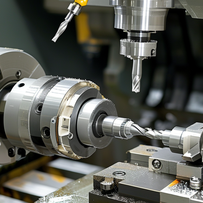
Identify the Spindle Motor Shaft’s Role in Your Machining System
How to Choose the Right Spindle Motor Shaft?
Identify the Spindle Motor Shaft’s Role in Your Machining System
A spindle motor shaft does more than rotate a cutting tool. It transfers motor torque through bearings, a tool holder, and the cutting interface. Its design affects cutting stability, positioning accuracy, heat control, and service life. Choosing it requires understanding the entire machining system, not only the motor rating.
Start with the required speed, torque, and cutting forces. A small shaft may flex during heavy milling, causing chatter and uneven surfaces. A larger shaft can improve stiffness, but it may increase rotational inertia and starting demands. Check the shaft diameter, material, hardness, keyway, taper, and connection dimensions. These details must match the bearings and tool-holding system precisely.
Measure runout near the tool interface. Even a few microns can matter during high-speed finishing. Review the cooling path, because heat can change shaft expansion and bearing preload. In practical machine evaluations, technicians sometimes focus too heavily on peak speed. That approach can miss low-speed torque and repeated side loading. An imperfect assumption can be costly. Confirm actual cutting conditions, duty cycles, lubrication, and maintenance access before selecting the shaft. Test under realistic loads when possible, rather than trusting catalog figures alone.
How to Choose the Right Spindle Motor Shaft? - Identify the Spindle Motor Shaft’s Role in Your Machining System
| Selection Dimension | Role in the Machining System | Typical Data or Range | How to Select the Shaft | Risk if Incorrectly Selected |
|---|---|---|---|---|
| Primary Function | Transfers motor torque to the cutting tool while maintaining tool position and rotational accuracy. | Torque transmission, tool location, radial support, axial positioning, and high-speed rotation. | Start with the machining process, cutting force, tool interface, maximum speed, and required accuracy. | Chatter, poor surface finish, excessive vibration, tool movement, or premature spindle failure. |
| Required Torque | Determines the shaft's ability to resist twisting during cutting. | Calculated from motor power and speed: T = 9550 × P ÷ n, where T is N·m, P is kW, and n is r/min. | Select a shaft with sufficient torsional strength for continuous torque and temporary peak torque. Include a practical safety margin. | Permanent twisting, fatigue cracking, loss of angular accuracy, or shaft fracture. |
| Maximum Spindle Speed | Controls centrifugal loading, bearing stress, heat generation, and dynamic stability. | Common machining spindle ranges include approximately 3,000–6,000 r/min for heavy cutting, 8,000–15,000 r/min for general machining, and 18,000–30,000 r/min for high-speed cutting. | Verify the shaft's critical speed, balance grade, bearing arrangement, and thermal behavior at the required operating speed. | Resonance, abnormal noise, overheating, excessive runout, or catastrophic mechanical damage. |
| Shaft Diameter | Affects torsional stiffness, bending stiffness, bearing capacity, and overall spindle rigidity. | Small precision spindles may use shaft diameters around 15–30 mm; medium machining spindles commonly use approximately 30–60 mm; heavy-duty designs may require larger diameters. | Increase diameter when cutting forces, tool overhang, or required rigidity increase. Confirm compatibility with bearings and the tool interface. | Deflection, reduced dimensional accuracy, chatter, bearing overload, or insufficient tool support. |
| Tool Interface | Connects the shaft to the tool holder or cutting tool and determines torque transfer and tool positioning. | Typical interfaces include taper systems, cylindrical collet seats, threaded noses, and hydraulic or shrink-fit tool connections. | Match the shaft nose geometry, taper angle, retention method, tool-holder size, and automatic tool-change requirements. | Tool slippage, incorrect seating, poor repeatability, increased runout, or inability to change tools. |
| Radial Runout | Indicates how far the rotating tool interface deviates from its ideal axis. | Precision machining may require runout of approximately 0.005–0.010 mm at the tool interface; general-purpose systems may permit higher values depending on the process. | Specify the runout at a defined measurement location and speed. Consider shaft accuracy, bearings, tool holder, and assembly cleanliness together. | Uneven tool wear, oversized holes, poor surface finish, vibration, and reduced tool life. |
| Axial Stiffness | Resists movement along the spindle axis during drilling, boring, plunging, and interrupted cutting. | Depends on shaft geometry, bearing preload, bearing spacing, housing stiffness, and tool overhang. | Choose a shaft and bearing arrangement that can withstand the expected axial cutting force without excessive displacement. | Hole-depth errors, tool deflection, dimensional variation, and unstable cutting. |
| Bending Stiffness | Limits radial deflection caused by cutting forces and tool overhang. | Bending stiffness increases strongly with shaft diameter; for a solid circular shaft, area moment of inertia varies with the fourth power of diameter. | Use the shortest practical tool extension and select a larger or more rigid shaft for deep cuts and long tools. | Tapered cuts, dimensional errors, chatter, and premature tool failure. |
| Material and Heat Treatment | Provides strength, fatigue resistance, wear resistance, and dimensional stability. | Spindle shafts are commonly produced from alloy steels and may use hardening, tempering, carburizing, nitriding, or precision grinding. | Specify mechanical properties, hardened surfaces where needed, corrosion protection, and dimensional stability after heat treatment. | Surface wear, fretting, fatigue damage, distortion, and shortened service life. |
| Bearing Compatibility | Supports the shaft while controlling radial and axial motion at the required speed. | Bearing selection depends on speed rating, load capacity, preload, precision class, lubrication, and operating temperature. | Match shaft fits, shoulders, preload requirements, bearing spacing, and lubrication method with the spindle design. | Bearing creep, overheating, vibration, excessive runout, or reduced bearing life. |
| Balance Quality | Controls vibration caused by mass imbalance during rotation. | High-speed spindle assemblies are dynamically balanced; the required balance quality depends on speed, tool mass, and process sensitivity. | Balance the complete rotating assembly, including the shaft, tool holder, drawbar components, and other rotating parts where applicable. | Vibration, noise, bearing damage, poor surface quality, and reduced maximum speed. |
| Cooling and Lubrication | Removes heat from bearings, the shaft, and the motor assembly while preserving dimensional accuracy. | Common approaches include air cooling, liquid jacket cooling, grease lubrication, oil-air lubrication, and oil mist systems. | Select the shaft and sealing arrangement according to speed, duty cycle, heat generation, coolant exposure, and maintenance requirements. | Thermal growth, lubricant degradation, seal failure, dimensional drift, and spindle seizure. |
| Axial Retention System | Maintains tool-holder contact and prevents axial movement during acceleration and cutting. | May use a drawbar, threaded retention, collet mechanism, hydraulic clamping, or shrink-fit retention. | Verify clamping force, retention geometry, release mechanism, balance, and compatibility with the tool-change cycle. | Tool pull-out, axial movement, inaccurate cuts, and damage to the spindle nose. |
| Operating Duty Cycle | Defines how long the shaft and spindle must operate under load before cooling or rest periods. | Light intermittent cutting, continuous roughing, high-speed finishing, and frequent acceleration impose different thermal and fatigue demands. | Use continuous torque, peak torque, acceleration frequency, daily operating hours, and thermal limits as design inputs. | Thermal overload, fatigue failure, inconsistent accuracy, and shortened component life. |
| Recommended Verification | Confirms that the selected shaft performs correctly as part of the complete spindle system. | Check torque, speed, runout, vibration, temperature rise, axial displacement, tool retention, and noise. | Test the assembled spindle under representative cutting conditions rather than evaluating the shaft alone. | Unexpected field failures, unstable machining, rework, and higher maintenance costs. |